Page 103 - LVS2023
P. 103

DRT / DRF
 Lighting for Vision System  LVS E-mail  >>  lvs@lvs.co.kr  102             Internet Web Service  >>  www.lvs.co.kr  103


 HIGH SPEED PWM POWER SUPPLIES  DN Series                                                                             DLA2 / DL
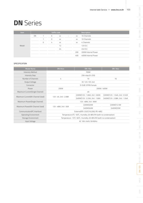
 DN Series


                  Item
                                                                     16 Channels
                             DN      1      6 Suffix code xx  -  xx  Description                                      DB / DB2
                                     1      0     xx            xx   10 Channels
 ANALOG DIMMING                      0      4     xx            xx   4 Channels
 CONTROLLER      Model                            12                 12V D.C                                          IFRK
                                                  24                 24V D.C
                                                                200  200W Internal Power
                                                                                                                      ILA-R/ILA-S
                                                                400  400W Internal Power


            SPECIFICATION

                      Model Name                 DN-04xx                DN-10xx               DN-16xx                 IDM
                     Intensity Method                                    PWM
                      Intensity Step                                 256-step (0-255)
 LVS-DN-1612        Number of Channels             4                      10                    16                    IFS
                     Output Voltage                                  DC 12V / DC 24V
                       Connector                                    D-SUB 37PIN Female
                        Power                     200W                           200W / 400W
               Maximum Current(Single Channel)                            4A                                          DDM
                                                                [200W]12V : 1.66A, 24V : 0.83A  [200W]12V : 1.04A, 24V : 0.52A
               Maximum Current(All-Channel Used)  12V : 4A, 24V : 2.08A
 ●    Instead of using the existing micro-computer CPU, 32bit CPU CORE embedded in the FPGA   [400W]12V : 3.33A, 24V : 1.66A  [400W]12V : 2.08A, 24V : 1.04A
 Product Feature  chip is used to maximize the response rate and stability  Maximum Power(Single Channel)  12V : 48W, 24V : 96W  [200W]12.5W  ICFV / ICFV2
                                                                      [200W]20W
 ●    The wattage is available in 200W and 300W  Maximum Power(All-Channel Used)  12V : 48W, 24V : 50A  [400W]40W  [400W]25W
 ●    The brightness can be adjusted using the knob on the front panel or through communication   Communication(PC Interface)  External[RS-232C(19,200), RS-485]  IFD
 using RS232 or RS485  Operating Environment         Temperature 0℃~30℃, Humidity 20-80% RH (with no condensation)
 ●    Using the RS485 communication, up to 64 units of the controllers can be connected simultaneously  Storage Environment  Temperature -15℃~60℃, Humidity 20-85% RH (with no condensation)
                                                                                                                      SHL / SVL
                      Input Voltage                                AC 100-240V, 50/60Hz


 LCD

 Brightness  ① LCD                                                                                                    UV / IR
 Control Knob
 PAGE UP   All 16 channel levels are shown
 PUSH ENTER
 ② PAGE UP
 CHANNEL                                                                                                              HLS
 PAGE DOWN
 Moves up to the corresponding channel
 !  WARNING
 !  ※ Do not open
      except stakeholders.
 ③ PAGE DOWN                                                                                                          EN / ES  /  ET
 RS485 Comm.  Moves down to the corresponding channel
 A(+), B(-)  RS485 Comm.
 Termination Switch
 Main Trans  ④ CONTROL KNOB
 Port (FPGA)
 RS232 Comm.                                                                                                          DN / DS
 MAIN POWER  M/T  RS 485  RS-232C  Turning the knob controls the brightness level
 SWITCH  1 6  9 5  TERMINATION  1  5
 6  9   PWM Output
 ON     OFF  ⑤ Press and hold the knob for 3 seconds to
 OUTPUT
 AC 220V Input  1
 save values to the flash memory.                                                                                     HPLS
 14  Signal Input
 MODE
 AC 90~264 VAC/47~63Hz
 2A/115 VAC/1.1A/230 VAC
 Mode Switch
                                                                                                                      UVH
   98   99   100   101   102   103   104   105   106   107   108